-
|
.
|
| 1) Can I create dxf files from DevFus 4 and DevWing 3 or do I need to buy the CAM versions to do this?
You need the Cam version if you need to work with a 3 axis cnc
2) If I purchase the usb stick can my existing Profili Pro license be transferred to it?
No |
|
-
|
.
|
| | Manually resize the topmost window of devWing and check the setting menu about the child windows size |
|
-
|
.
|
| Most common causes are:
- bad kerf settings
- wrong placement of the block in the cutting table (for tapered panels)
- wrong carriage distance settings (for tapered panels) |
|
-
|
.
|
| | You can just ignore that page, if you don't need side shaping. |
|
-
|
.
|
| | See the "Apply also to Brother Blocks" check box placed below the Block list |
|
-
|
.
|
| | Apply the geodetic rib and set the last regular rib as phantom |
|
-
|
.
|
| See the options in the bottom/left side of the dialog, to control the way the hot wire travels in the upper and lower sides.
Read well the Help file, as well... |
|
-
|
.
|
| When a .DAT file is describing an airfoil, it must follow these rules:
- The first row must include the airfoil name, following rows the x y coordinates, separated by blank spaces and using a dot (.) as decimal separator
- The airfoil must be drawn with the chord horizontal, and the Leading edge at the left side
- The x coordinates must be normalized in the 0.0 - 1.0 range.
- The y coordinates must have the chord value placed at 0.0
- The polyline describing the airfoil shape must start from the Trailing edge, with counter clockwise orientation
- The polyline describing the airfoil shape cannot include intersections, zero length segments, or sharp corners
- If the Trailing edge has a thickness greater than 0.0, the polyline describing the airfoil shape must be opened at the Trailing edge
- The nose must be smooth.
- If a part of the polyline describing the airfoil shape is straight (for example in the low side of a Clark Y), multiple coordinates must be used to describe the straight part, as well. Or Smoothing features will probably then modify that line to create a smoother shape.
You can use for example devCad Pro 3 to create or correct a polyline to these rules, then select it and export as a .DAT file |
|
-
|
.
|
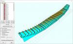
| Bulding tab planform
 |
|
-
|
.
|
| | All times that problem was reported, the cause was an unshielded wire for limit switches. |
|
-
|
.
|
| When you cut wing panel with different length, that affect the way they can be placed inside the Foam block (whose length is at least the length of the longer wing panel).
If you cut panels with the same length, these options don't produce effects.
Try to cut panel with different length and you will see in the differences in the top view 2D preview.
From the Help menu:
Block faces align/placement along the foam length:
May be you selected Blocks having different lengths, or you specified a Foam Block length larger than the length of this Block. In this case you can specify how/where to place the Block in the Foam block along the Block length axes (carriages distance).
Possible options are:
Place the Block in the middle of the Foam block
Align the Root face of the Block to the Foam block face
Align the Tip face of the Block to the Foam block face
Once You specified an alignment option, you can also apply an offset, see next parameter
Optional additional offset, internal for the aligned cases :
This value is applied as an offset to the above alignment. This value is applied for the first case as positive from left to right carriages.
For the other cases positive means the Block moved inside the Foam block. |
|
-
|
.
|
| Some pictures of my hi-tech testing device 
I started the development of the new sketch for my Arduino Mega + Ramps controller.
Done:
- Management of 5 interpolated axes. 4 axes for the 2 carriages and 1 optional rotary axes. All the 5 axes can be driven on the same GCode command, so also complex cut can be performed
- Stepper pulse supplied by interrupt writing on internal register using low level assembler like commands. In this way the max speed and time accuracy can be performed, with the possibility to make other work (GCode parsing, look-ahead, acceleration/deceleration computing and so on without affecting the smoothness of the motors run)
- The most difficult thing: to make the input output pin selection not written at code level, as done for example by Grbl and Marlin, but fully customizable at runtime.
In this way if for example I want to change the wiring, use a different shield than Ramps, I haven't do modify the sketch code, ricompile and upload it again, but just set them by the Setting menu of devCnc Foam.
And I can select the pin in the way I prefer, Grbl for example can run only pin on the same port, limiting the max axes number to 4.
To do:
- hot wire management. I'll test the PWM output included in Ramp for the hot table (max 24v x 11A).
- limit switches. I want make them customizable as pin, and managed at firmware side, to be faster to intercept an alarm. Will be available a Switch for each linear axes.
- devCnc Foam - Arduino communication protocol. I want to use less bandwidth than the usual application, so I can have a more accurate 3D preview.
That's all, back to work.... |
|
-
|
.
|
| At the right temperature you should see the so called 'angel hair', if you cut by contact.
Probably nothing if you cut by irradiation. |
|
-
21 replies since 4/4/2012
.
